Voltage Interface Node in Ames, Spain
Used
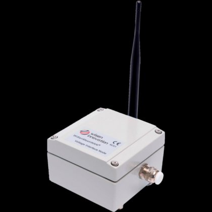
Doubleclick to zoom in
Contact the seller for
additional photos and information.
Specifications
- Condition
- used
- Battery power
- 1 primary lithium battery 3.6V type D (ER34615)
- Stopping voltage for precision
- 2.7VDC
- Stopping voltage for mesh network
- 2.1VDC
- Battery connection
- Standard aluminum battery holder
- Working current (dc)
- Max. 210mA
- Local storage
- Minimum 450 messages during mesh connection
- Dimensions (l x w x h)
- Interface node: 100 x 100 x 60 mm
- Weight
- 0.6 kg
- Size and weight of the external sensor
- Depends on the connected sensor (external cable length ≤ 1.0 m)
- Strain relief
- 1 x EMC-CMA12 for external sensor connection
- Cable entry
- Spring terminal
- Precision
- 0.05% F.E. (full scale)
- Resolution
- 0.18 mV
- Temperature
- Range: -40 to 85°C; Accuracy: ±1°C; Resolution: 0.1°C
- Voltage
- Accuracy: ±0.1V
- Mesh wireless interface
- WiSenMeshWAN® Protocol
- Switch position
- Output Voltage (Vcc_Out)
- 0 (default)
- 1.8V (por defecto)
- 1
- 2.5V
- 2
- 3.3V
- 3
- 5.0V
- Example
- For model 6C01, Vcc_Out must be set to 2.5V to power an EC-5 soil moisture sensor and allow the node to sample between 0 and 2.5V.
- Attention
- For other sensors, check their specifications before configuring.
- Category
- Sensors in Spain
- Subcategory
- Wireless sensors
- Subcategory 2
- Rail & monitoring
- Listing ID
- 110771309
Description
Voltage-type sensors with Vin = 1.8V / 2.5V / 3.3V / 5.0V, current required ≤ 100mA, sensor output signal (Vout) ≤ sensor input voltage (Vin).
The WiSenMeshWAN® system offers dynamic and autonomous wireless data acquisition of geotechnical sensors using cutting-edge technology. Automated measurement of geotechnical sensors, using long-range wireless radio nodes and a SmartGateway, allows you to focus on more demanding tasks instead of manual data acquisition and recording.
WiSenMeshWAN® sensor nodes are transmitters and receivers that form a self-assembled dynamic radio mesh network that sends data to a SmartGateway. Users have full remote control of the system through direct, activated or programmed changes, enabling dynamic measurements and reporting
0–1.8V → 1.8V ± 0.05V
0–2.5V → 2.5V ± 0.05V
0–3.3V → 3.3V ± 0.05V
0–5.0V → 5.0V ± 0.05V